Showing posts with label DP32. Show all posts

Wednesday, 29 April 2015

ChipKIT DP32 I2C Bus Speed with a MCP4725 DAC

Both arduino and MPIDE seem to have the I2C bus speed set to 100 kHz by default. So, here it is how to change it to 400kHz.
Inside the MPIDE folder, go to hardware\pic32\libraries\Wire\utility.
Inside file twi.h Find the string #define TWI_FREQ 100000 and change it to:  #defineTWI_FREQ 400000.
In my simple test i went from a 20Hz sinewave to a 72Hz just by effecting this change to the bus speed.
On the DP32 Board, SDA is assigned to Pin RB9 and SCL to Pin RB8.


Tuesday, 2 September 2014

Binary counter- 6 bit r2r DAC example for chipKit DP32 - PIC32MX250F128B

/*
Dubworks 6 bit r2r DAC example u4 LSB's using board leds 
 to display ;for chipKit DP32 board - PIC32MX250F128B
 @2014
 */
unsigned int i=0;
void setup(){
  Serial.begin(19200);
  LATBCLR = 0x3F;  // BIN 111111 ; 0xF for 4 leds only
  TRISBCLR =0x3F;  // Ports RB0-RB5 as Output ; 0xF for 4 leds only
}
void loop(){
  LATBCLR = 0x3F; //  clear 0xF for 4 leds only
  LATB |= i ;
  int a;
  a=PORTB;

  Serial.println(" I DEC ");
  Serial.println(i,DEC);
  Serial.println(" PORTD BIN ");
  Serial.println(a,BIN);

  i++;
  /* if you want to use the 5 bits of port B 0-4 */
  //  if(i < = 32){
  //    i=0; 
  //  }

  if(i < = 64){
    i=0;  
  }

  delay(250); //

}


note : P0-05 == RB0-RB5 ports

Tuesday, 29 July 2014

Dub && Wise Synth


*some decoupling capacitors 100nFclose to the analog pins should be added.


My initial intention was to create something focused for the soundsystem culture. This turned out to be much more difficult than i thought .
Dub siren/Elec tom synth/And oscilattor+ MAD Lfos (some trying to recreate some of the sounds in a synare that Jah Shaka got us all used to)...All this synthesized on the fly with the help of some wavetables (all created during the start up)
.
Pots for :
-Oscillator wave selector ( Sine,cosine  Saw, Inverted Saw, Square wave, triangle and 1 extra slots for now )
-LFO rate
-LFO modulator type select ( Any of the above tables, plus a few more specific and tailored options)
-Attack
-Release
* Both attack and release can interact with the LFO
- Mode selector ( Dub Siren, Sound effects " a la Synare", Elec-Tom synth)

This video is just as an update on the proceedings.
Here i am using the Arduino Due.
Due to its complexity, i ended up re-writing the whole code from scratch and fresh to suit this specific idea.
Already started porting a similar idea to the chipKit DP32, and Pinguino and an Xmos version also soon to come, subject to availability of spare time.


Tuesday, 12 November 2013

PLBP for chipKit DP32 { Proverbial (4) Led Blink Program }


Ok I just could not resist, and had to post the Proverbial Led blink Program adapted for the DP32, that has 4 LED's on the board ( Digital Pins 11 to 14).
Will scroll them from right to left, speed varying on the variable resistor on board( trim pot).


/* Proverbial (4) Led Blink Program
 
 Scrolls 4 light emitting diodes(LED), by turning on and off connected to 4 different digital  
 pins, using the delay() function and the current millis alike :) . 
 
 The circuit:
 * 4 LED's on board - pins D11, D12, D13 and D14 
 ** Variable resistor/trimpot on A2
 
 *** Version done for the chipKit board DP32 **
 ****  http://dubworks.blogspot.co.uk/
 */

// constants won't change. Used here to 
// set pin numbers:
const int ledPin =  11;      // the number of the LED pin
const int ledPin1 =  12; 
const int ledPin2 =  13; 
const int ledPin3 =  14; 
int i;
// Variables will change:
int ledState = LOW;             // ledState used to set the LED
int ledState1 = LOW;
int ledState2 = LOW;
int ledState3 = LOW;
long previousMillis = 0;        // will store last time LED was updated

// the follow variables is a long because the time, measured in miliseconds,
// will quickly become a bigger number than can be stored in an int.
//long interval = 500;           // interval at which to blink (milliseconds)

void setup() {
  // set the digital pin as output:
  pinMode(ledPin, OUTPUT);
  pinMode(ledPin1, OUTPUT);
  pinMode(ledPin2, OUTPUT);
  pinMode(ledPin3, OUTPUT);
  pinMode(A2, INPUT);
  ledState = !ledState;  //Toggle the bits to start
  ledState1 = !ledState1;
  ledState2 = !ledState2;
  ledState3 = !ledState3;  
}

void loop()
{
  boolean b; 
  long interval = analogRead(A2); // interval at which to enter function.(milliseconds)
  interval= interval/3; //So it is not too slow
  digitalWrite(ledPin, ledState);
  digitalWrite(ledPin1, ledState1);
  digitalWrite(ledPin2, ledState2);
  digitalWrite(ledPin3, ledState3); 
  // 

  // check to see if it's time 
  unsigned long currentMillis = millis();

  if(currentMillis - previousMillis > interval) {
    // save the last time  
    previousMillis = currentMillis;   
    // 
    int var;
    var=interval-(currentMillis - previousMillis);
    // conditional depending on increment accumulator
    if(!b){
      switch (i) {

      case 0 :    
        ledState = !ledState;
        digitalWrite(ledPin, ledState); 
        delay((var*0.5));
        break;

      case 1 :    
        ledState1 = !ledState1;
        digitalWrite(ledPin1, ledState1); 
        delay((var));
        break;

      case 2 :    
        ledState2 = !ledState2;
        digitalWrite(ledPin2, ledState2); 
        delay((var*1.5));
        break;

      case 3 :    
        ledState3 = !ledState3;
        digitalWrite(ledPin3, ledState3); 
        delay((var*2));
        break;

      default:
        b=!b;
        break;
      }
    }
    else{
      switch (i) {

      case 0 :    
        ledState = !ledState;
        digitalWrite(ledPin, ledState); 
        delay((var*2.5));
        break;

      case 1 :    
        ledState1 = !ledState1;
        digitalWrite(ledPin1, ledState1); 
        delay((var*3));
        break;

      case 2 :    
        ledState2 = !ledState2;
        digitalWrite(ledPin2, ledState2); 
        delay((var*3.5));
        break;

      case 3 :    
        ledState3 = !ledState3;
        digitalWrite(ledPin3, ledState3); 
        delay((var*4));
        break;

      default:
        b=!b;
        break;
      }
    }
    i++; // Increment our accumulator
    i=i%5; 
    // Keep the value within  the parameters needed for our switch case
    // in this case 5, so we can have 4 + 1 
    // (0, 1, 2 and 3) + 1 for default toggling of boolean variable b. (aesthetic reasons ?!)  
  }
}


Saturday, 2 November 2013

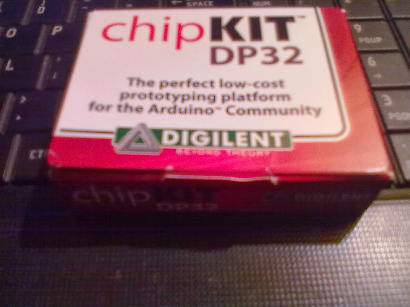
A DP32 chipKit from Dangerous prototypes... for free ?!? Yes Please !!


As some of you might have noticed, i love to dig into,  learn with, bash my head against, and ultimately discover new platforms. In my perspective it is essential to develop new and wide skills that ultimately will make one a better prepared and experienced programmer and engineer !
Recently i have been looking into the PIC32 as the most probable option to the Retro-inspired drum-synth i been developing for quite a while now, despite the fact i been using several chips along the way to develop ideas for the final version.

So, i took my chance and proposed an idea i been working in for a while, as part of a Dangerous Prototypes give-away with Microchip and Diligent in the form of a contest .
And guess what ?! I won !

QUOTE
Another winner is Ras B, and his idea for a CHipKit version of a Retro-Inspired Cynare Drum Synth scored him a chipKIT DP 32:
Id use the DP32 to make a CHipKit version of a Retro-Inspired Cynare Drum Synth( ADSR with variable exponential attack, LFO’s included) and some additional features ( Modulation related Like phaser, flanger and some basic reverb and delay- This through an additional memory chip to allow some leverage in the chips memory limitations) 
I am still working on implementing some of it, while a lot of it i have or am currently implementing it
* Funny thing was i was actually working on it when , during a break, i came across the news that i'd won !! :) .

I have already worked with the dip version of the PIC32 , even posted about it.
And i am not sure as yet, if all these features are all possible in a DIP version of it ( as it only runs at around 40 MHz, compared with th 80MHz of SMD versions).
But i vow to make a lighter version ( if need be) for the dip version, as i love it myself.
There are some limitations that might become an issue to take it as far as intend , due to the abstraction created by higher level languages as the "Arduino-based" used by the MPIDE. But, bit by bit (pass the pun) , i intend to present any limitations i might come across and reference them, so it helps anyone else !