A new version of the Arduino IDE (1.6.3) is available at the download page!
The Arduino IDE 1.6.3 is a bug fix release: after the already released 1.6.2 with new libraries and cores managers.http://blog.arduino.cc/2015/04/02/arduino-ide-1-6-3-released-and-available-for-download/
Showing posts with label Arduino DUE. Show all posts
Showing posts with label Arduino DUE. Show all posts
Tuesday, 14 April 2015

Tuesday, 29 July 2014
Dub && Wise Synth

*some decoupling capacitors 100nFclose to the analog pins should be added.
My initial intention was to create something focused for the soundsystem culture. This turned out to be much more difficult than i thought .
Dub siren/Elec tom synth/And oscilattor+ MAD Lfos (some trying to recreate some of the sounds in a synare that Jah Shaka got us all used to)...All this synthesized on the fly with the help of some wavetables (all created during the start up)
.
Pots for :
-Oscillator wave selector ( Sine,cosine Saw, Inverted Saw, Square wave, triangle and 1 extra slots for now )
-LFO rate
-LFO modulator type select ( Any of the above tables, plus a few more specific and tailored options)
-Attack
-Release
* Both attack and release can interact with the LFO
- Mode selector ( Dub Siren, Sound effects " a la Synare", Elec-Tom synth)
This video is just as an update on the proceedings.
Here i am using the Arduino Due.
Due to its complexity, i ended up re-writing the whole code from scratch and fresh to suit this specific idea.
Already started porting a similar idea to the chipKit DP32, and Pinguino and an Xmos version also soon to come, subject to availability of spare time.

Monday, 30 September 2013
Quick-Benchmark on LUT / sine wavetable generation with DUE

During my research for my "secret" project i decided to benchmark sine wave and sine wave LOOK UP TABLE's generation, the different methods and approximations, both mathematically and methods for discrete time systems like uC's.
For research purposes, and initial development i have been actually using the Arduino Due, due to its ease of testing and debugging initial stages of ideas , for which the DAC helps a lot.
I been guessing already some limitations speed performance (considering what i want to achieve) in later stages, but for now it has been a brilliant tool.
As the ARM in the DUE was a new thing to me, and to shorten the time, i had to look around for some initial guidance regarding the registers/tmers and interrupts in order to get started.
In that sense Duane B.'s work and Groovuino's with their QUICK 'N' DIRTY synth were invaluable.
At the moment, im quite advanced, and it came to mind to use some "live" sine calculations for some other purposes other than the Pure-tone sinewave itself ( complex sinusoids and subsequent modulation, etc).
So decided to benchmark both thei sinewavetable generation and a somewhat adapted version i used previously.
And using the millis() in Arduino, there was almost a halving of time taken to generate 512 samples of wavetable.
Duane's version took 27/28 Ms contrasting with 16/17 Ms.
Now, while this is not relevant for their synths, it is to me. Specially when im trying to squeeze as many cycles as i can already with the arduino Due, due to all the layers that the "easy way" places in between, massively contributing to the decrease in performance of speed/time. :)
Its easy to see where the optimization is, slightly reducing the cycles needed !
Some surprises soon, and some more on this as well...
Table_1 test code
#define WAVE_SAMPLES 512
long previousMillis = 0;
// default int is 32 bit, in most cases its best to use uint32_t but for large arrays its better to use smaller
// data types if possible, here we are storing 12 bit samples in 16 bit ints
#define offset 2047 // In this case is the same as the Amplitude
uint16_t sin_data[WAVE_SAMPLES];
float w ;    // ψ
float yi ;
float phase;
int sign_samp;
int i;

void create2nd_sine (){
  // Serial.println(" ");
  // Serial.println("Sine table2");
  w=(2.0 * PI)/WAVE_SAMPLES;
  for (i = 0; i <= 511; i++)
  {
    yi= offset*sin(phase); // Offset is the same as the Amplitude
    phase=phase+w;
sign_samp=offset+yi; // dc offset translated for a 12 bit DAC sin_data[i]=sign_samp; // write value into array // Serial.println(i); // Serial.println(sin_data[i]); } } // void setup() { // put your setup code here, to run once: Serial.begin(9600); } void loop() { // put your main code here, to run repeatedly: unsigned int result; unsigned long currentMillis = millis(); create2nd_sine (); result=currentMillis - previousMillis; previousMillis = currentMillis; Serial.println(result); }Table_2 test code
// Duane's
#define WAVE_SAMPLES 512
// default int is 32 bit, in most cases its best to use uint32_t but for large arrays its better to use smaller
// data types if possible, here we are storing 12 bit samples in 16 bit ints
uint16_t nSineTable[WAVE_SAMPLES];
long previousMillis = 0;

void createSineTable()
{
  //   Serial.println(" ");
  //   Serial.println("Sine table");
  for(uint32_t nIndex = 0;nIndex < WAVE_SAMPLES;nIndex++)
  {
    // normalised to 12 bit range 0-4095
    nSineTable[nIndex] = (uint16_t)  (((1+sin(((2.0*PI)/WAVE_SAMPLES)*nIndex))*4095.0)/2);
    //  Serial.println(nIndex);
    //  Serial.println(nSineTable[nIndex]);
  }
}
//

void setup() {
  // put your setup code here, to run once:
  Serial.begin(9600);
}

void loop() {
  // put your main code here, to run repeatedly:
  unsigned int result;
  unsigned long currentMillis = millis();
  createSineTable();
  result=currentMillis - previousMillis;
  previousMillis = currentMillis;
  Serial.println(result);
}
For a more detailed explanation of a sinewave generator, and a few diff methods, check below link
(1) http://dubworks.blogspot.co.uk/p/blog-page.html
Sunday, 1 September 2013
Simple sine wave generator template in C

As i only used a limited amplitude on the sine wave generator for Arduino Due's DAC, im posting a template here that should help you make the necessary changes( someone asked me this).
This specific template code was written for C code in Codeblocks for Gcc, so you will have to be able to know the differences.
# include < stdio.h >
# include < stdlib.h >
# include < math.h >
# define n_points 32 //256 is ideal for microcontrollers or highers if youre computing complex sinusoids
int main ()
{
float pi = 3.141592;
float w ; // ψ
float yi ;
float phase;
int sign_samp;
int sin_data[n_points]; // sine LUT Array
int i;
w= 2*pi;
w= w/n_points;
for (i = 0; i <= n_points; i++)
{
yi= 2047*sin(phase);
phase=phase+w;
sign_samp=2047+yi; // dc offset translated for a 12 bit DAC
//sign_samp+= b; // Add adc value; Keep it at zero for pure sine
sin_data[i]=sign_samp; // write value into array
/*
*/
}
for (i = 0; i <= n_points; i++)
{
int k=sin_data[i];
printf ("sine is %d\n", k);
printf ("i is ... %d\n", i);
}
float x;
printf ("Enter a number ... \n");
scanf ("%f", &x); // keeps the debugging console on codeblocks open ;)
return 0;
}


Pseudo-code
"Two random variables were talking in a bar. They thought they were being discrete but I heard their chatter continuously "
(1) Signal Processing for Communications by Paolo Prandoni and Martin Vetterli
(2) http://dubworks.blogspot.co.uk/p/blog-page.html
Wednesday, 3 April 2013
Sinewave Generator with the DAC of the ARM SAM3X -The Code

   /* Discrete Computational Methods */

    /* Generating/Sample discrete sinusoid */

/* Direct digital synthesis is a common technique for generating
waveforms digitally. The principles of the technique are simple and
widely applicable. You can build a DDS oscillator in hardware or in
software.
A DDS oscillator is sometimes also known as a Numerically-Controlled
Oscillator (NCO). Usually we use a Circular buffer or FIFO.
The NCO function contains a sine look-up tables (LUTs) that perform
the following functions:
sin(n) = sin(2πn/N)
where:
n = Address input to the LUT
N = Number of samples in the LUT
sin(n) = Amplitude of sine wave at (2πn/N)

Incrementing n from 0 to N causes the LUT to output one complete
cycle of amplitude values for the sine  function. The value 2πn/N
represents a fractional phase angle between 0 and 2π. The time (t)
required to increment n from 0 to N is the period of the sine
waveforms produced by the NCO function.

The LUT address is incremented once each system clock cycle by an
amount equal to the phase input. The phase angle data is accumulated
and stored in the phase accumulator register. The output of the
phase accumulator register is used to address the LUTs.
The frequency (f) of the system clock (fCLK) is fixed. Therefore,
the frequency of the sine waves is:
f = 1/t = fCLK × phase/2π. */
            /*  Table Lookup */
 /*The table look-up method precomputes the unique samples of every
 output sinusoid at the start of the simulation, and recalls the
 samples from memory as needed. Because a table of finite length
 can only be constructedif all output sequences repeat, the method
 requires that the period ofevery sinusoid in the output be evenly
 divisible by the sample period. That is, 1/(fiTs) = ki must be
 an integer value for every channel i = 1, 2, ..., N.
 The table that is constructed for each channel contains ki elements.
 For long output sequences, the table look-up method requires
 far fewer floating-point operations than any of the other methods,
 but may demand considerably more memory, especially for high
 sample rates (long tables). This is the recommended method
 for models that are intended to emulate or generate code for DSP
 hardware, and that therefore need to be optimized for execution speed.*/
       /*  Differential */
 /* The differential method uses an incremental (differential) algorithm
rather than one based on absolute time.
This mode offers reduced computational load, but is subject to drift
over time due to cumulative quantization error.
Because the method is not contingent on an absolute time value,
there is no danger of discontinuity during extended operations (when
an absolute time variable might overflow). */
        /* Trigonometric Function */
 /*  If the period of every sinusoid in the output is evenly divisible
 by the sample  period, meaning that
1/(fiTs) = ki is an integer for every output yi, then the sinusoidal
output in the ith channel is a repeating sequence with a period of
ki samples. At each sample time, the block evaluates the sine function
at the appropriate time value within the first cycle of the sinusoid.
By constraining trigonometric evaluations to the first cycle of each
sinusoid, the block avoids the imprecision of computing the sine of
very large numbers, and eliminates the possibility of discontinuity
during extended operations (when an absolute time variable might
overflow). This method therefore avoids the memory demands of the table
look-up method at the expense of many more floating-point operations. */
               /*  - THE CODE -  */
/*Used the proverbial timer interrupt example code, and
the old techniques on Direct digital synthesis available at
places like
http://interface.khm.de/index.php/lab/experiments/arduino-dds-sinewave-generator/
or
http://rcarduino.blogspot.co.uk/2012/12/arduino-due-dds-part-1-sinewaves-and.html
*/


// variables accessed by the interrupt
volatile byte adc;
volatile byte out_sign;
volatile boolean l;

  float pi = 3.141592;
  float w ;    // ψ
  float yi ;
  float phase;
  int D = 1024;
  byte sign_samp;
  byte sin_data[1024];  // sine LUT Array
  int icounter;
  int counter2;
  int testPin = 13;      // debugging pin digital pin 13
  int testPin2 = 12;      // debugging pin digital pin 12
  int testPin3 = 11;      // debugging pin digital pin 11
  int testPin4 = 10;      // debugging pin digital pin 11
  float a;
  float b;

void setup()
    {
      fill_sinewave();       // load memory with sine table
      pinMode(testPin,OUTPUT);
      pinMode(testPin2,OUTPUT);
      pinMode(testPin3,OUTPUT);
      pinMode(testPin4,OUTPUT);
      startTimer(TC1, 0, TC3_IRQn, 0x8000); //TC1 channel 0, the IRQ
      // for that channel and the desired frequency - 32768 -see somewhere
      // else for the reason why
      analogWrite(DAC0,0);  //Duane B// this is a cheat - enable the DAC
    }

void loop()
    {
      counter2++;           //
      if (counter2 >= 0x400)
        {
          digitalWrite(13, l = !l); // toggle debugging pin on pin 13
          counter2=0;
          fill_sinewave();
        }
      adc=analogRead (0);  // get the adc
      b=analogRead(1);     // get the adc 2
         if(b<=511)
          {
            b=b*pi/128;
          }
      else if (b>=512)
          {
            b=b/16;
          }
      if (adc<=249)
          {
            a=2;
          }
      if (adc>=250 && adc<=511)
          {
          a=4;
          }
      if (adc>=512 && adc<=750)
          {
            a=6;
          }
      if (adc>=851 && adc<=1024)
          {
            a=8;
          }
      digitalWrite(12, l = !l);     // toggle debugging pin on pin 12
    }
    /*
* Here is the table of parameters: *
  ISR/IRQ TC      Channel Due   pins
  TC0 TC0 0 2,      13
  TC1 TC0 1 60,     61
  TC2 TC0 2 58
  TC3 TC1 0 none  <- this line in the example above
  TC4 TC1 1 none
  TC5 TC1 2 none
  TC6 TC2 0 4, 5
  TC7 TC2 1 3, 10
  TC8 TC2 2 11, 12
*/

void startTimer(Tc *tc, uint32_t channel, IRQn_Type irq, uint32_t frequency) {
  pmc_set_writeprotect(false);
  pmc_enable_periph_clk((uint32_t)irq);
  TC_Configure(tc, channel, TC_CMR_WAVE | TC_CMR_WAVSEL_UP_RC | TC_CMR_TCCLKS_TIMER_CLOCK1);
  uint32_t rc = VARIANT_MCK/8/frequency; //8 because we selected TIMER_CLOCK1 above
  TC_SetRA(tc, channel, rc/2); //50% high, 50% low
  TC_SetRC(tc, channel, rc);
  TC_Start(tc, channel);
  tc->TC_CHANNEL[channel].TC_IER=TC_IER_CPCS;
  tc->TC_CHANNEL[channel].TC_IDR=~TC_IER_CPCS;
  NVIC_EnableIRQ(irq);
}
// TC1 ch 0
void TC3_Handler()
    {
      digitalWrite(10, l = !l);    // toggle debugging pin on pin 10
      TC_GetStatus(TC1, 0);
      icounter++;                  // increment index
      //icounter=icounter + b;         // Variable frequency with potentiometer
      icounter = icounter & 0x3ff;         // limit index 0..1023
      if( icounter==0x400)
        {
          icounter=0;
        }
      out_sign=sin_data[icounter];
      dacc_write_conversion_data(DACC_INTERFACE, out_sign);
    }

       /*  Plotting Complex Sinusoids as Circular Motion  */
             /*             */
/* Euler's relation graphically as it applies to sinusoids. A point
traveling with uniform velocity around a circle with radius 1 may
be represented by  */
       /* eiφ = cos(φ) + i*sin(φ) */
            /*   eψt=eψft    */
/* in the complex plane, where:
  t is time and  is the number of revolutions per second.
  e is Euler's number, the base of natural logarithms,
  i is the imaginary unit, which satisfies i2 = −1, and
  π is pi, the ratio of the circumference of a circle to its diameter.
(1) http://en.wikipedia.org/wiki/Sound
(2) http://en.wikipedia.org/wiki/Sound_frequency
(3) http://en.wikipedia.org/wiki/Sine_wave
(4) https://ccrma.stanford.edu/~jos/Welcome.html
(5) http://lionel.cordesses.free.fr/gpages/DDS1.pdf
*/
void fill_sinewave()
    {
      digitalWrite(11, l = !l);  // toggle debugging pin on pin 11
      w= a*pi;
      w= w/512;  // sine LUT Array D= ox8000(fs)@32Hz. at  use 512
//The shape of the stored waveform is 64Hz
// arbitrary, and can be a sinusoid, a square, sawtooth, etc // fill the 1024 byte circular ring buffer array for (D = 0; D <= 0x3ff; D++) { yi= 0x7f*sin(phase); // try yi= 0x7f*sin(phase)-(2*cos(phase)); // increase to 3 ? yi= A*sin(phase)- cos(phase)- cos(phase)- cos(phase); phase=phase+w; // 0 to 2xpi - 1/1024 increments sign_samp=0x7f+yi; // dc offset sign_samp+= b; // Add adc value; Keep it at zero for pure sine sin_data[D]=sign_samp; // write value into array /* */ } digitalWrite(11, l = !l); // toggle debugging pin on pin 11 }http://dubworks.blogspot.co.uk/p/blog-page.html
- Chec my related post with a slightly refined code template

Monday, 1 April 2013
sinewave generator with the DAC of the ARM SAM3X

On my adventures in Digital signal processing and sound synthesis, i started to do some experiments...
First was to do a sinewave generator with the DAC of the Arduino DUE and the timer interrupt at 4096 samples per second. I know its not much for the ARM core of the SAM3X chip that clocks at 84Mhz, but was a exercise more than anything. This is quite scalable, anyway !
Direct digital synthesis is a common technique for generating waveforms digitally. The principles of the technique are simple and widely applicable. You can build a DDS oscillator in hardware or in software.A DDS oscillator is sometimes also known as a Numerically-Controlled Oscillator (NCO).
Usually we use a Circular buffer or FIFO.
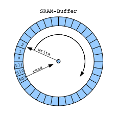
The NCO function contains a sine look-up tables (LUTs) that perform the following functions:
sin(n) = sin(2πn/N)
where:
n = Address input to the LUT
N = Number of samples in the LUT
sin(n) = Amplitude of sine wave at (2πn/N)
Incrementing n from 0 to N causes the LUT to output one complete cycle of amplitude values for the sine function. The value 2πn/N represents a fractional phase angle between 0 and 2π. The time (t) required to increment n from 0 to N is the period of the sine waveforms produced by the NCO function.
The LUT address is incremented once each system clock cycle by an amount equal to the phase input. The phase angle data is accumulated and stored in the phase accumulator register. The output of the phase accumulator register is used to address the LUTs.
The frequency (f) of the system clock (fCLK) is fixed. Therefore, the frequency of the sine waves is:
f = 1/t = fCLK × phase/2π.
As a taster of the code to come (Used the proverbial timer interrupt example code, and the old techniques on Direct digital synthesis available at places like interface.khm.de) .Ill leave you some pictures
Mine is the picture below (1st), below is the output of a grain synth , code available at rcarduino.blogspot.co.uk.
*The sinewave generator code i shall share is not the one at this link above, but an " original " one !.
Also had to mention the wicked BASIC program i been using to help me in my math algorithms called "Decimal BASIC", available at http://hp.vector.co.jp/authors/VA008683/english/.
The sine wave graphic at the top is from it !!


Subscribe to:
Posts (Atom)