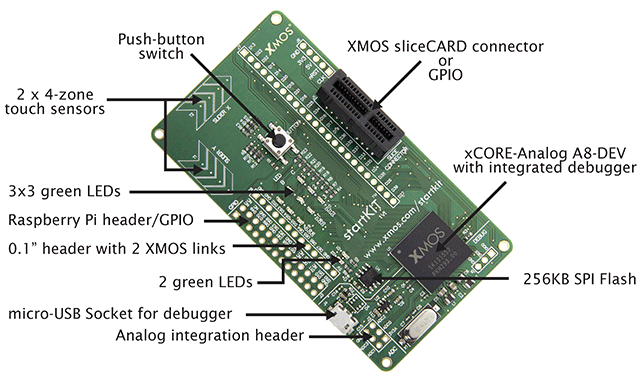
Wow, Many thanks to XMOS Ltd , Bristol, for sending me their new XMOS multicore dev board, with an ARM A8 processor (8 cores), and compatibility with Raspberry pi pin-out connector ! A
As a gift ! Must be Christmas, then ! :)
"500MIPS xCORE multicore microcontroller has eight 32bit logical cores that perform deterministically"
http://www.xmos.com/startkit/what
Electronics, Synth, Sound effects, Microcontrollers, , Digital signal processing,AVR, PIC, PIC32,ARM, etc
Showing posts with label ARM. Show all posts
Friday, 13 December 2013
Monday, 30 September 2013
Quick-Benchmark on LUT / sine wavetable generation with DUE
During my research for my "secret" project i decided to benchmark sine wave and sine wave LOOK UP TABLE's generation, the different methods and approximations, both mathematically and methods for discrete time systems like uC's.
For research purposes, and initial development i have been actually using the Arduino Due, due to its ease of testing and debugging initial stages of ideas , for which the DAC helps a lot.
I been guessing already some limitations speed performance (considering what i want to achieve) in later stages, but for now it has been a brilliant tool.
As the ARM in the DUE was a new thing to me, and to shorten the time, i had to look around for some initial guidance regarding the registers/tmers and interrupts in order to get started.
In that sense Duane B.'s work and Groovuino's with their QUICK 'N' DIRTY synth were invaluable.
At the moment, im quite advanced, and it came to mind to use some "live" sine calculations for some other purposes other than the Pure-tone sinewave itself ( complex sinusoids and subsequent modulation, etc).
So decided to benchmark both thei sinewavetable generation and a somewhat adapted version i used previously.
And using the millis() in Arduino, there was almost a halving of time taken to generate 512 samples of wavetable.
Duane's version took 27/28 Ms contrasting with 16/17 Ms.
Now, while this is not relevant for their synths, it is to me. Specially when im trying to squeeze as many cycles as i can already with the arduino Due, due to all the layers that the "easy way" places in between, massively contributing to the decrease in performance of speed/time. :)
Its easy to see where the optimization is, slightly reducing the cycles needed !
Some surprises soon, and some more on this as well...
Table_1 test code
#define WAVE_SAMPLES 512 long previousMillis = 0; // default int is 32 bit, in most cases its best to use uint32_t but for large arrays its better to use smaller // data types if possible, here we are storing 12 bit samples in 16 bit ints #define offset 2047 // In this case is the same as the Amplitude uint16_t sin_data[WAVE_SAMPLES]; float w ; // ψ float yi ; float phase; int sign_samp; int i; void create2nd_sine (){ // Serial.println(" "); // Serial.println("Sine table2"); w=(2.0 * PI)/WAVE_SAMPLES; for (i = 0; i <= 511; i++) { yi= offset*sin(phase); // Offset is the same as the Amplitude phase=phase+w;
sign_samp=offset+yi; // dc offset translated for a 12 bit DAC sin_data[i]=sign_samp; // write value into array // Serial.println(i); // Serial.println(sin_data[i]); } } // void setup() { // put your setup code here, to run once: Serial.begin(9600); } void loop() { // put your main code here, to run repeatedly: unsigned int result; unsigned long currentMillis = millis(); create2nd_sine (); result=currentMillis - previousMillis; previousMillis = currentMillis; Serial.println(result); }Table_2 test code
// Duane's
#define WAVE_SAMPLES 512 // default int is 32 bit, in most cases its best to use uint32_t but for large arrays its better to use smaller // data types if possible, here we are storing 12 bit samples in 16 bit ints uint16_t nSineTable[WAVE_SAMPLES]; long previousMillis = 0; void createSineTable() { // Serial.println(" "); // Serial.println("Sine table"); for(uint32_t nIndex = 0;nIndex < WAVE_SAMPLES;nIndex++) { // normalised to 12 bit range 0-4095 nSineTable[nIndex] = (uint16_t) (((1+sin(((2.0*PI)/WAVE_SAMPLES)*nIndex))*4095.0)/2); // Serial.println(nIndex); // Serial.println(nSineTable[nIndex]); } } // void setup() { // put your setup code here, to run once: Serial.begin(9600); } void loop() { // put your main code here, to run repeatedly: unsigned int result; unsigned long currentMillis = millis(); createSineTable(); result=currentMillis - previousMillis; previousMillis = currentMillis; Serial.println(result); }For a more detailed explanation of a sinewave generator, and a few diff methods, check below link
(1) http://dubworks.blogspot.co.uk/p/blog-page.html
Monday, 1 April 2013
sinewave generator with the DAC of the ARM SAM3X
On my adventures in Digital signal processing and sound synthesis, i started to do some experiments...
First was to do a sinewave generator with the DAC of the Arduino DUE and the timer interrupt at 4096 samples per second. I know its not much for the ARM core of the SAM3X chip that clocks at 84Mhz, but was a exercise more than anything. This is quite scalable, anyway !
Direct digital synthesis is a common technique for generating waveforms digitally. The principles of the technique are simple and widely applicable. You can build a DDS oscillator in hardware or in software.A DDS oscillator is sometimes also known as a Numerically-Controlled Oscillator (NCO).
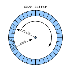
Usually we use a Circular buffer or FIFO.
The NCO function contains a sine look-up tables (LUTs) that perform the following functions:
sin(n) = sin(2πn/N)
where:
n = Address input to the LUT
N = Number of samples in the LUT
sin(n) = Amplitude of sine wave at (2πn/N)
Incrementing n from 0 to N causes the LUT to output one complete cycle of amplitude values for the sine function. The value 2πn/N represents a fractional phase angle between 0 and 2π. The time (t) required to increment n from 0 to N is the period of the sine waveforms produced by the NCO function.
The LUT address is incremented once each system clock cycle by an amount equal to the phase input. The phase angle data is accumulated and stored in the phase accumulator register. The output of the phase accumulator register is used to address the LUTs.
The frequency (f) of the system clock (fCLK) is fixed. Therefore, the frequency of the sine waves is:
f = 1/t = fCLK × phase/2π.
As a taster of the code to come (Used the proverbial timer interrupt example code, and the old techniques on Direct digital synthesis available at places like interface.khm.de) .Ill leave you some pictures
Mine is the picture below (1st), below is the output of a grain synth , code available at rcarduino.blogspot.co.uk.
*The sinewave generator code i shall share is not the one at this link above, but an " original " one !.
Also had to mention the wicked BASIC program i been using to help me in my math algorithms called "Decimal BASIC", available at http://hp.vector.co.jp/authors/VA008683/english/.
The sine wave graphic at the top is from it !!
Labels:
32,
Arduino,
Arduino DUE,
ARM,
ARM SAM3X,
C Programming,
DubWorks,
electronics,
SAM3X,
Theory
Subscribe to:
Posts (Atom)