 |
| Nice smooth startup |
Breadboarding/testing dc inverter with 5532 op amp and a simple Frequency Generator with arduino ( with passive LP and HP before op-amp) .
And with this last stage, i think i got a nice buffered line-level output for the Effects chain/dubsiren design.
It boiled down to the choice of either TI LMC7660, the Microchip TC1044 or this one. As it is audio and op-amps i think the compromise was the 1054, which can deliver up to 100mA, tuned slightly faster to reduce too much noise passing to the audio ( i will regulate both rails anyway from a higher voltage dc source like a 12 Volts average wall adapter).
Saves me messing about with AC centre tapped transformers.
And definitely did not want to rely on capacitive coupling alone, as not safe enough . 100 ma should allow me up to two 5532's for stereo in and stereo out buffers.
 |
| 555 example circuit |
For much simpler needs , a 555 can be useful as dc inverter , but not necessarily with audio beyond some guitar pedals designs maybe. 50mA unregulated, maybe 20 mA regulated. And it is load susceptible...
 |
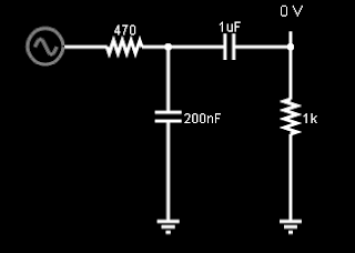
| Filter used with arduino PWM-dac |
Same for high pass :1K resistor and1uF capacitor 1/(2 pi *1000*0.000001) = 159.154943092
 |
| Arduino PWM out( @15625 Sampling) producing a 30 hz out through filter ... mad distortion an phase issues |
 |
| "But you could low pass before the op-amp and couple it with HP after the buffer to improve the situation" . Yes i could... but do i want to in this case ? Maybe in another. |
 |
| And here is why : It peaks at 1.7v !! A well worth compromise in a design with an atmega 328 or similar |
 |
| Pic from https://www.electronicshub.org/passive-low-pass-rc-filters/ |

